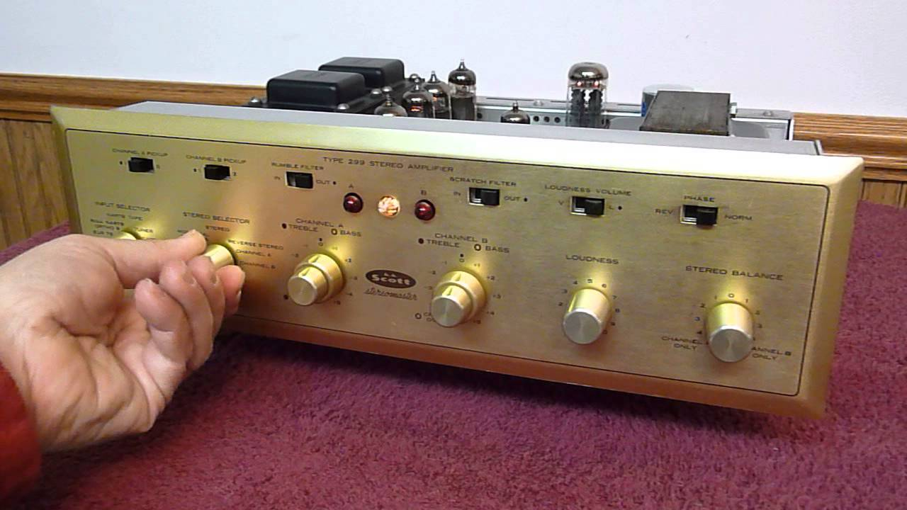
- HH SCOTT STEREO MASTER TYPE 314 DRIVER
- HH SCOTT STEREO MASTER TYPE 314 MODS
- HH SCOTT STEREO MASTER TYPE 314 FREE
HH SCOTT STEREO MASTER TYPE 314 DRIVER
Next trial is changing the npn driver pull up resistor from dynaco 1.5 kohm to AX6 3.3 kohm. Lubuntu op system has an electronic layout feature, but no simulations.
HH SCOTT STEREO MASTER TYPE 314 FREE
I'm in a bland mid-western Spice free zone, all my Windows op systems get destroyed by microsoft since nobody will give me or sell me the source disk with these used computers. At last, some modern ideas about quasi-comp. It is lighting the AC light bulb pretty bright after the 33 ohm mod.īy deleting the feedback transistor, replacing it with a speaker capacitor, and feedback through an emitter resistor on the input transistor, (Original ST120and Pwg-Tang circuit) I think I can manage to fit this output stage on my board. I've been modding Pwg Tang one part at a time to the Apex AX6 and find I've got 480 ma bias at this point, with pnp driver emiter resistor changed from dynaco 3.3 ohm to AX6 33 (his 27 ohm), and an output transistor emitter 0.5 ohm resistor added. Fortunately the fans I added took care of the heat. That is worse than the defective djoffe feedback bias circuit I am replacing which with the current mirror broken was putting out 220 ma bias current. On Nema C laminate, and find it is fixed bias 380 ma whatever the position of the bias pot is. I've just built the quasi comp Pwg-Tang modification to ths dynaco ST120 driver board,
HH SCOTT STEREO MASTER TYPE 314 MODS
The text version of the Bauxendall and Shaw mods was way over my head. Thanks for drawing all this out Mooly & Ygg-it, and for the panasonic SU380 source schematic. Now compare the upper combination R314 TR308 R318 arrangement to the lower side, R317 TR309, Re. TR308 has an emitter resistor, TR309 has none. The two NPN transistors are not loaded equally. Once you see that, you know where to put the added C & D, in parallel to R316. One ADDS the parallel loads to TR307's emitter to mimic what TR306 sees. That's where the Shaw and Baxandall modifications come in. The parallel effect of the output transistor is missing. The effective load on the NPN driver is R314||diode||capacitor. That base looks like a diode and a capacitor in parallel. The sch shows the NPN driver emitter loaded with R314||baseTR308 What the diode/capacitor/resistor do is ensure the NPN and PNP driver transistors see equal loading on their emitters. The Quasi output stage only occurs at the two NPN devices. I should add a 10nF~22nF parallel capacitor but I cannot see the pic here. PS: I'm trying to simulate with MicroCAP: the problem are the missing models.

The amplifier is National Panasonic SA-73 (1971)ġ) Is it better a power diode across R319 (1 Ohm) or a transdiode across R366 (39 ohm)Ģ) Can I add directly in parallel or I have to change any components, like rise R316 equal to R317 (180 ohm)? Which resistor value in parallel?ģ) Should I have to add a few nF capacitor in parallel ?Ĥ) Which diode/transistor type do you suggest (see below cross ref)? I would like to maintain a vintage configuration so i need to add components exsisting in the seventiesĥ) What voltage/bias level I should read to be sure that everything works, after adding the Baxandall? Hello can you please help me to add a Baxandall transdiode or diode across R139 or (may be better) across R316 without doing a disaster?


 0 kommentar(er)
